The importance of position and attitude
System topology
The following figure shows an imaging sensor and its dependencies on a rotational encoder, a global positioning system (GPS) and an inertial measurement unit (IMU). The imaging sensor has an internal coordinate system. The imaging sensor is attached to a rotating arm. A rotational encoder provides an observation of the arm’s position. We can define the dependency of the imaging sensor’s coordinate system to the rotational encoder’s coordinate system. The image sensor and the rotational encoder are attached to a platform, perhaps an aircraft or a satellite. The internal coordinate system of the rotational encoder can be defined in terms of the platform’s internal coordinate system. The GPS and the IMU determine the platform’s internal coordinate system relation to the standard datum, the Earth coordinate system.
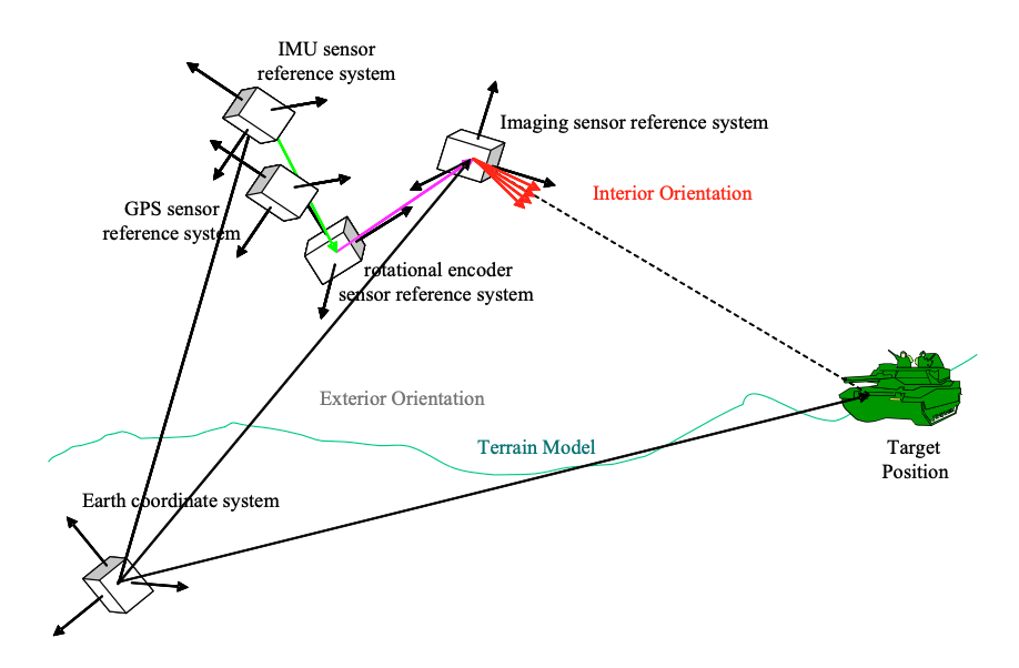
Figure 2 Conceptual representation of a sensor system
Figure 3 shows a dependency graph, or topology, of the sensors shown in Figure 2. We will use these dependencies to define the calculations of the origin of the imaging sensor energy.
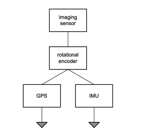
Figure 3 Dependency graph of sensor system
Kinematics
Kinematics is the science of motion which treats motion without regard to the forces which cause it1. Most work in kinematics is focused on robotics. However, the same calculations and equations are necessary in sensor fusion. It is not without surprise that the US National Institute for Standards and Technology (NIST) efforts in sensor fusion arose from its robotics laboratory. Our objective is to resolve the origin of the sensor energy relative to a standard datum, which we have chosen as earth-centered earth-fixed (ECEF). The energy is known relative to the sensor’s internal coordinate system. In our example, the sensor of interest is an imaging sensor. We must translate the imaging sensor’s internal coordinate system to the ECEF coordinate system through a series of translations determined by the dependency graph shown in [].
There are many ways to translate coordinate systems. We will standardize on what is named the ZYX Euler angles as shown in Figure 5. It prescribes the following algorithm:
- Rotate around the Z axis at an angle ω (omega).
- Rotate around the resulting Y axis at angle φ (phi).
- Rotate around the resulting X axis at angle κ (kappa)
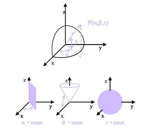
Figure 4 Polar coordinate system
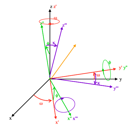
Figure 5 ZYX Euler transformation
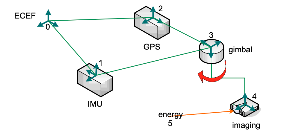
Figure 5 Example transducer system
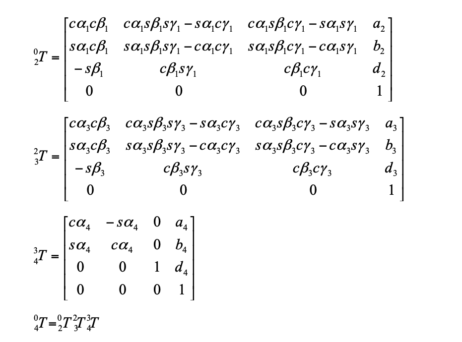
To determine the origin of the energy, we must transform the energy vector from the image sensor coordinate system T4 to the standard ECEF coordinate system T0. There are seven changing values in these transforms. The rest are constants. The angles (α1, β1, γ1) are the angle readings from the IMU. The distances (a2, b2, d2) are the position readings from the GPS. All of these readings are relative to the ECEF. The angle (α4) is the reading from the rotation encoder. The change in the coordinate system can only occur along this one angle. The gimbal is fixed to the platform, so the angles (α3, β3, γ3) and the distances (a3, b3, d3) are all constants. Similarly, the image sensor is fixed to the gimbal arm, so the distances (a4, b4, d4) are constants as well.
Complex topologies
Figure 7 shows a more complex topology that contains eight sensors. The sensors are labeled with letters. The lines between the sensors indicate dependencies. Not all dependencies are related to geometry. The observation of one sensor can be the parameter of another sensor.
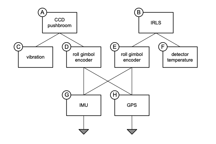
Figure 5 Complex sensor system dependencies
The following are the transducers in the system:
- A: charge coupled device (CCD) pushbroom scanner
- B: infrared line scanner (IRLS)
- C: vibration
- D: roll gimbol encoder
- E: roll gimbol encoder
- F: detector temperature
- G: inertial measurement unit (IMU)
- H: global positioning system (GPS)
The following lists the particular dependencies:
- A-C vibration
- A-D position and attitude
- B-E position and attitude
- B-F infrared detector temperature
- D-G attitude
- D-H position
- E-G attitude
- E-H position
In sensor fusion, we deal with ever increasing complex topologies. We want to be able to create ad hoc sensor topologies by combining existing systems into virtual systems. We can only do that if the internal dependencies of a system are exposed in a rigorous, normalized definition.
Footnotes
-
John J. Craig. Introduction to Robotics: Mechanics and Control. 2d ed. (Addison-Wesley: 1989) p6. ↩