Coordinate reference frame
The transducer coordinate reference frame is used to define the coordinate frame of the transducer’s IFOI. The transducer coordinate reference frame should be defined relative to an easily identified physical point on the transducer, such as the lower left hand corner or the center of mass. The transducer coordinate reference frame may even be outside the physical form of the transducer itself. The transducer coordinate reference frame is itself located at any point most convenient for defining the transducer’s IFOI.
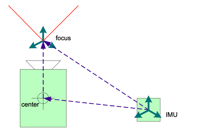
Figure 18 The coordinate reference frame of a transducer
For instance, in Figure 18 we show our example camera. The transducer coordinate reference frame is located at the pen-hole equivalent focus point in front of the lens. Since it is hard for a system designer to find the pen-hole equivalent focus point, we define the specific location of the transducer coordinate reference frame relative to the camera’s center of mass. Within a system description, we would further define the location of the camera’s transducer coordinate reference frame relative to another transducer coordinate reference frame, such as an inertial measurement unit (IMU).
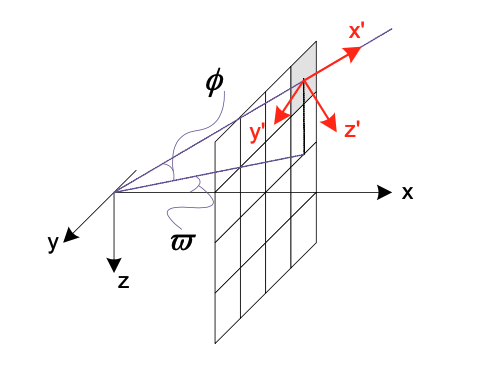
Figure 19 Translation of IFOI frame relative to the sensor frame
The purpose of the transducer coordinate reference frame is to provide a means to define the particular IFOI coordinate reference frame for each data element. We define the transducer coordinate reference frame such that is convenient for the definition of the IFOI coordinate reference frame. We are, in essence, describing which direction the IFOI points for each particular data element. We describe which direction the IFOI points by describing a Euler transformation relative to the transducer coordinate reference frame. By taking this approach, we remain consistent in how we calculate location for the system, the sensor and the data.
Figure 20 shows three different examples of how the IFOI frame is defined for different sensor types. Example (a) is a frame camera which has the IFOI rotate from negative omega to positive omega and from phi to negative phi. The lower left-hand corner pixel will be (-ω,- φ) and the upper right-hand corner will be (ω,φ). Example (b) is a push-broom sensor and example (c) is a conical scan sensor. All three sensor types can be described the same way, by the Euler transform of IFOI reference for each data element. What differs is simply the particular transforms.
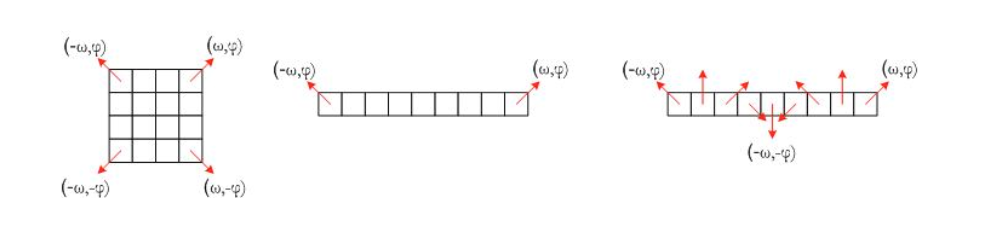
Figure 20 Translation of IFOI frame for (a) frame camera, (b) push broom and (c) conical scan sensors