Engineering diagrams
Software architecture diagrams suck.
My father and grandfather built houses. I grew up with blueprints, the large drawings used for construction. For those who may have never seen such drawings before, here is an example:
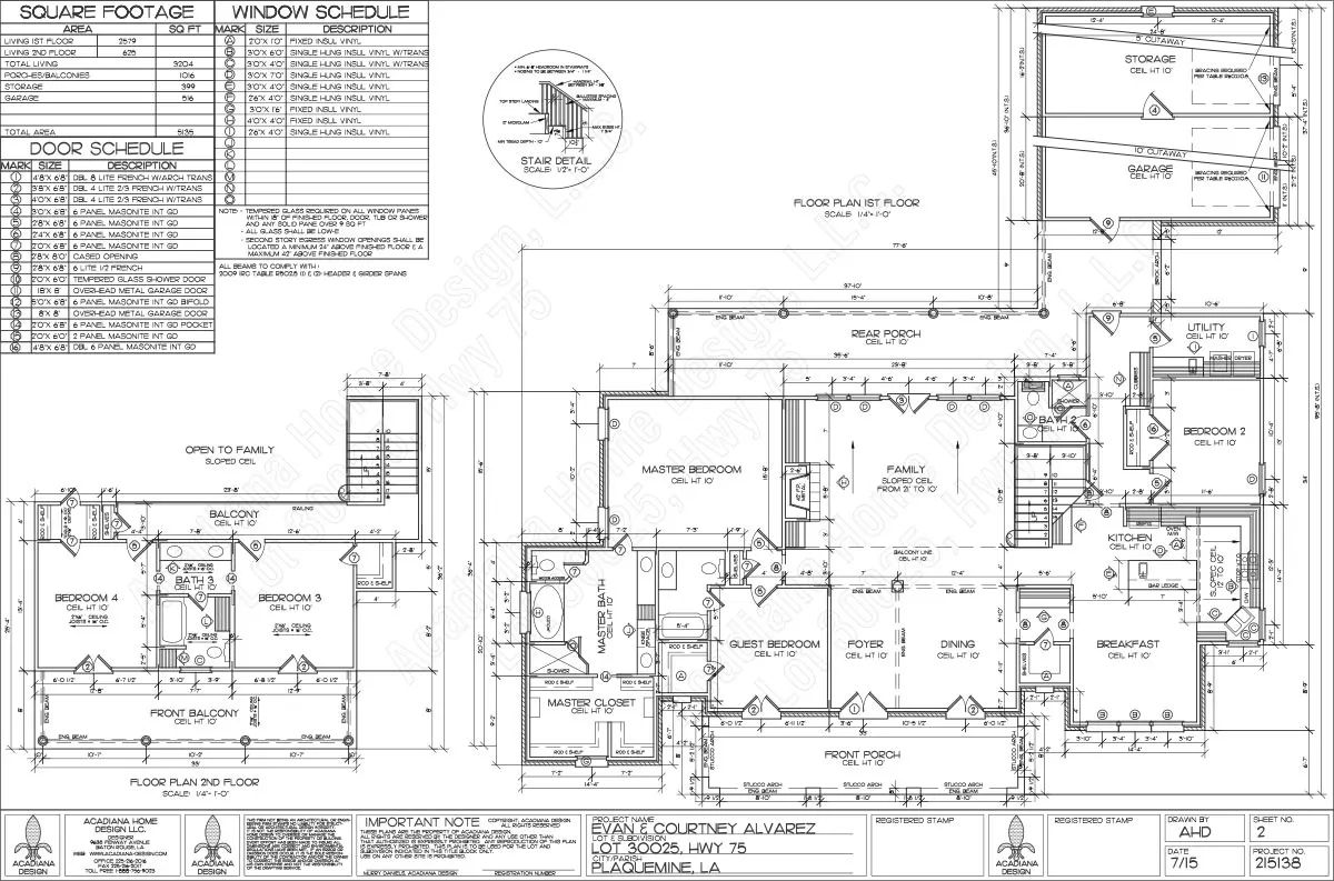
There is a specific, consistent graphical language that is used for creating such drawings. There are different standard subsets of the diagrams that are used for foundations, framing, plumbing and electrical. Builders and all the tradesmen learn how to read these diagrams. They (almost) never need to ask a question of the architect who drew them. The diagrams are self explanatory. That is only possible because all architects use the same standard system of conveying their designs.
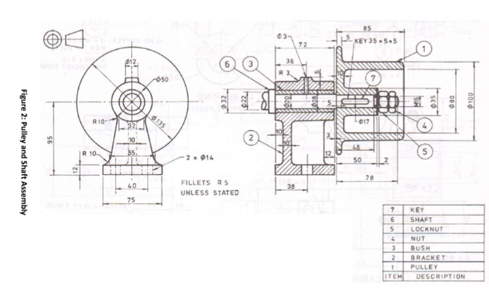
I was also educated as a mechanical engineer. Again, there is a graphical language that all mechanical engineers use. I can create a drawing and mail it to a fabrication shop. They should be able to build the item without ever asking me a question because the diagrams are self explanatory.
Not to belabor the point, but electrical engineers have the same thing; a graphical language that is consistently used so that others can understand and build their designs. The symbol for a capacitor or a resistor is always the same, no matter who is drawing it.
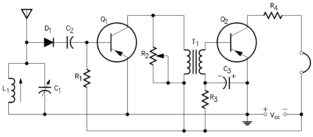
You can hand that diagram to any electrical engineer, and he can build that circuit.
Challenge
Now compare those disciplines to software. There are wild differences in so called software architecture drawings. Not one of these drawings can stand on its own without the person who drew it having to explain it. These items can mean different things, from drawing to drawing and even on the same page:
- Arrows
- Solid lines
- Dotted lines
- Boxes
- Box borders
- Nesting of boxes
- Lines connecting to box edges
- Lines crossing box edges
- Line labels
One source of the problem is that engineers try to convey all the information in one drawing, rather than making multiple drawings to explain the different aspects. In actual architecture, there are separate drawings for the framing details and the electrical details. Combining the details of both on the same drawing would be too confusing. Why should software engineers combine message sequencing and component hierarchy in the same diagram?
We must establish the same discipline in our software design and our business processes design. There must be standard graphical languages used for explaining our designs such that the diagram is self explanatory.
Possible solution
Here is a list of some defined graphical languages and how they apply to the design process.
- UML object model: code structure
- UML sequence diagram: message flow
- Business Process Model and Notation (BMPN): workflows
- C4 : software architecture
- IDEF0 : business modeling
Then again, perhaps none of these existing standards meet the challenge. Perhaps it is time to create a new graphical language for software?
Also see: Jakub Kapuscik, Modeling Software Architecture With C4